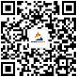
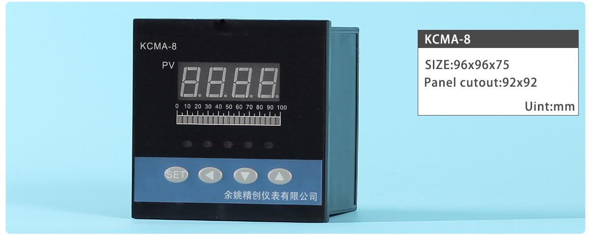
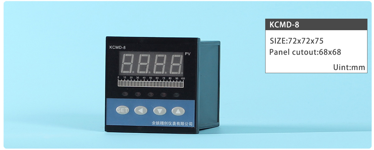
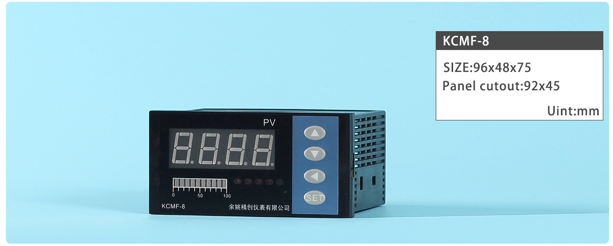
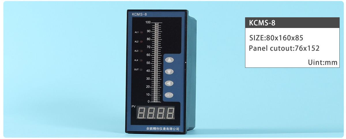
Types:KCMS-84T,KCME-84T,KCMF-84T,KCMD-84T,KCMA-84T
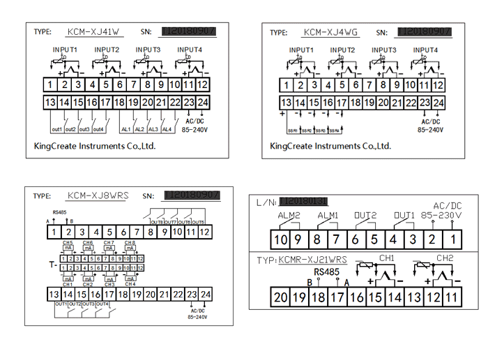
Terminal Arrangement:
| Register Address | Code | Name | Manual | Setting range | Ex-Factory |
|---|---|---|---|---|---|
| 0 | AL-1 | Alarm 1 | please refer to ALP1 | Depending on sensor type | 500.0 |
| 1 | HY-1 | Alarm Differential gap | Alarm relay contact may repeat its turning ON and OFF due to input fluctuation if measured value (PV) is near the alarm set value. An alarm differential gap setting can prevent the relay contact from ON or OFF repetition. | 0.1~100.0 | 0.5 |
| 2 | AL-2 | Alarm 2 | please refer to ALP2 | Depending on sensor type | 300.0 |
| 3 | HY-2 | Alarm Differential gap | Alarm2 Differential gap | 0.1~100.0 | 0.5 |
| 4 | AL-3 | Alarm 3 | please refer to ALP3 | Depending on sensor type | 800.0 |
| 5 | HY-3 | Alarm Differential gap | Alarm3 Differential gap | 0.1~100.0 | 0.5 |
| 6 | AL-4 | Alarm 4 | please refer to ALP4 | Depending on sensor type | 100.0 |
| 7 | HY-4 | Alarm Differential gap | Alarm4 Differential gap | 0.1~100.0 | 0.5 |
| 8 | LOCK | Set data lock | LOCK=18, Set data unlock LOCK≠18, Set data lock. |
0~250 | 18 |
| 9 | SC | PV Bias | The value set in the PV bias is added to the actual input value to correct the input value. | ±100.0 | 0.0 |
| 10 | DP | Decimal position | When thermocouple and thermal resistance input, the decimal point set up the range of 0~1; when current and voltage input ,the decimal point set up the range of 0~3. | 0~3 | 1 |
| 11 | P-SH | Range high | The control is displayed after Input range. | P-SL~9999 | 999.9 |
| 12 | P-SL | Range low | 0~P-SH | ||
| 13 | G-SH | Bar-Graph high | Light Bar-Graph Display high limit and lower limit. | G-SL~P-SH | 999.9 |
| 14 | G-SL | Bar-Graph low | P-SL~G-SH | ||
| 15 | PF | Digital Filter | This is a 1st-order lay filter by software prepared in order to reduce fluctuations of measured value (PV) by noise. | 0~99 | 20 |
| 16 | ALP1 | Alarm1 type | 0: Alarm function OFF; 1: Process high alarm 2: Process low alarm |
0~2 | 1 |
| 17 | ALP2 | Alarm2 type | |||
| 18 | ALP3 | Alarm3 type | |||
| 19 | ALP4 | Alarm4 type | |||
| 20 | ADDR | Address |
Communication address can be set from 0 to 255 | 0~255 | 1 |
| 21 | BAUD | Communication speed | 1200; 2400; 4800; 9600; | —— | 9600 |
Contact us| Legal declaration | Site map
KINGCREATE is a temperature controller design and manufacturing company in China. Innovate with 300+ analog Advanced Universal PID Temperature Controller with software, tools and the industry‘s largest sales/support staff.
© Copyright 2007-2024 KingCreate Instruments Co.,Ltd.