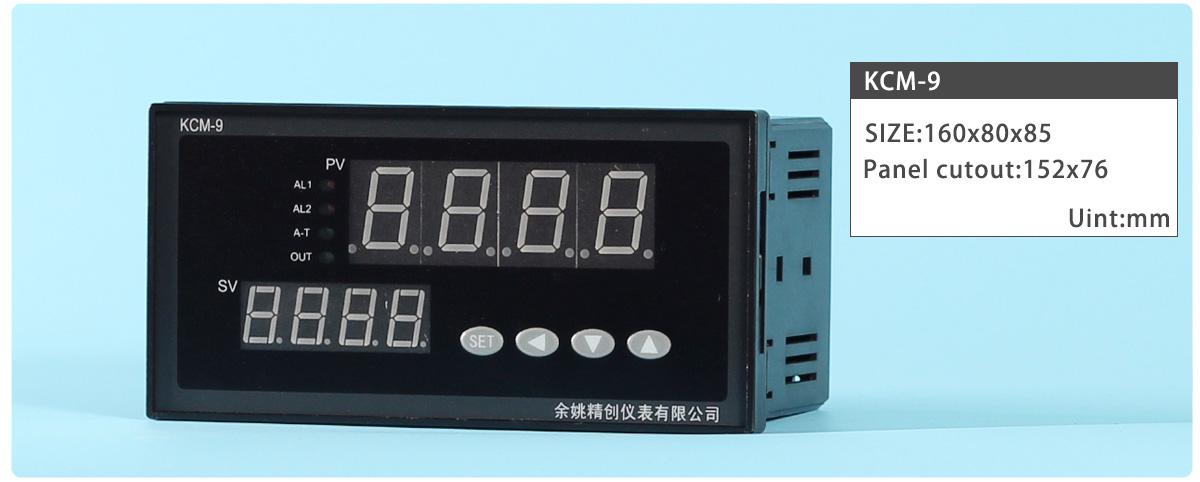
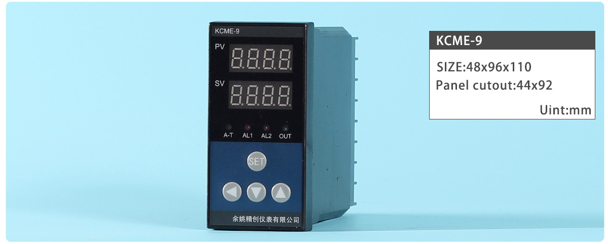
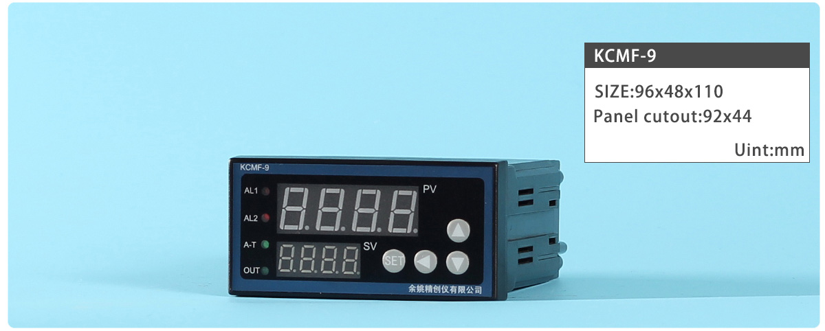
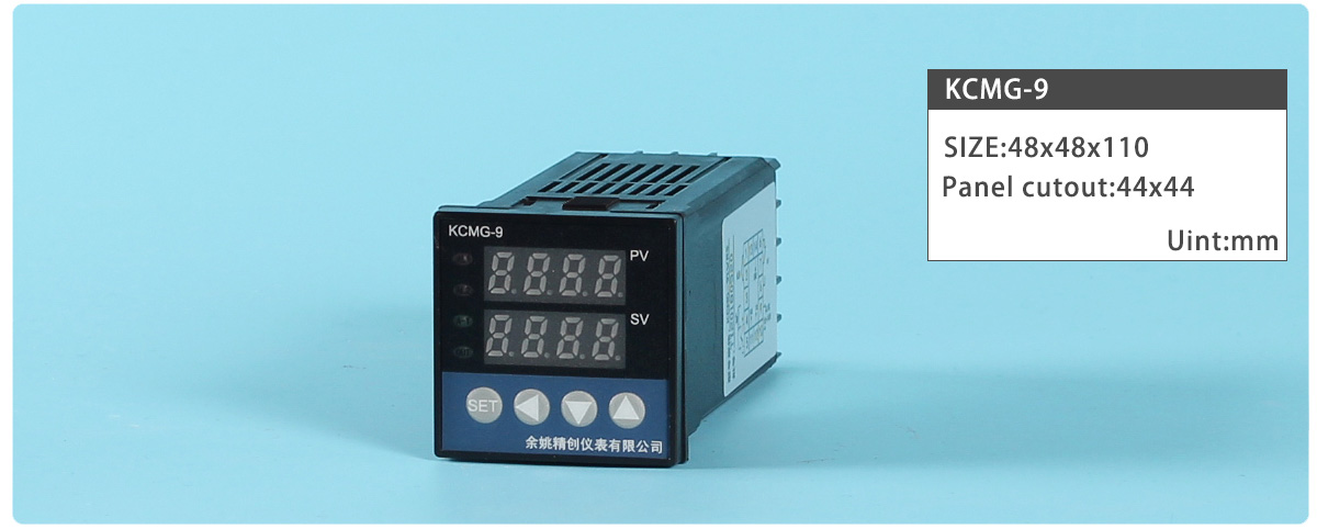
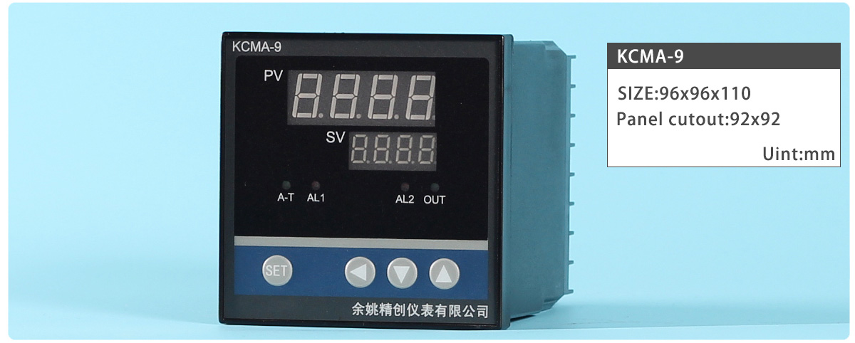
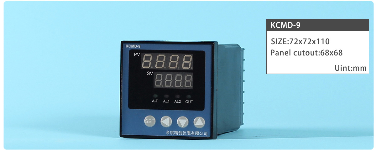
Types:KCMA-91A KCM-91A KCME-91A KCMF-91A KCMG-91A KCMD-91A KCMA-92A KCM-92A KCME-92A KCMF-92A KCMG-92A KCMD-92A
Terminal Arrangement:

| Register Address | Code | Name | Manual | Setting range | Ex-Factory |
|---|---|---|---|---|---|
| 0x00 | SP | Setting value | Set the temperature set value (SV) which is the target value for control | Determined by P-SL P-SH | - |
| 0x01 | AL-1 | Alarm 1 | Please refer to ALP for the alarm mode suitable. Alarming when the program sections is breaking up. |
- | |
| 0x02 | AL-2 | Alarm 2 | - | ||
| 0x03 | Pb | PV Bias | The value set in the PV bias is added to the actual input value to correct the input value. | ±20.0 | 0 |
| 0x04 | KP | Proportional band | Set when PI or PID control is performance. For heating / cooling PID action. When P=0,the meter is ON/OFF control |
0-3000 | 100 |
| 0x05 | KI | Integral time | Eliminates offset occurring in proportional control. | 0~3000 | 500 |
| 0x06 | KD | Derivative time | Prevents overshoot and/or undershoot caused by integral action effect.. | 0~2000S | 100S |
| 0x06 | KT | PID control cycle. | Control response time | 2~120 | 20 |
| 0x07 | FC | Digital Filter | This is a 1st-order lay filter by software prepared in order to reduce fluctuations of measured value (PV) by noise. | 0~50 | 20 |
| 0x08 | Hy | Differential gap | When the control is ON/OFF control(P=0) Relay contact may repeat its turning ON and OFF due to input fluctuation if measured value (PV) is near the alarm set value.the differential gap setting can prevent the relay contact from ON or OFF repetition. |
0.1~50.0 | 0.5 |
| 0x09 | dp | Decimal point position selection | Set the position of the decimal point for the measured value to be displayed. | 0~1 | 0 |
| 0x0A | outH | Output limiter high | Output limiter low to 200 | 200 | |
| 0x0B | outL | Output limiter low | 0 to Output limiter high | 0 | |
| 0x0C | AT | Autotuning (AT) with learning function | 1: Autotuning (AT) with learning start 0: Autotuning (AT) with learning stop Turns OFF automatically when the AT with learning function is completed. |
0~1 | 0 |
| 0x0D | LocK | Set data lock | LOCK=0, Set value (SV) and parameter can be set. LOCK=1,Only set value (SV) can be set. LOCK>1, Set value (SV) and parameter cannot be set. |
0~50 | 0 |
| 0x0E | ts | Input type1 | Cu50(–50.0~150.0℃); Pt100 (–199.9~600.0℃; ) K( -30.0~1300℃); E( -30.0~700.0℃); J (-30.0~900.0℃); T( -199.9~400.0℃); S( -30~1600℃); |
__ | K |
| 0x0F | Input type2 | 0~5V/0~10mA; 1~5V/4~20mA; |
__ | 4-20mA | |
| 0x10 | OP-A | Control output | 0:no output 1:Relay output 2:Voltage output (for driving SSR) 3:Zero-cross output(for driving Triac) 4:PID linear current output(4-20mA /0-10v) (A single functional) |
0~7 | READ ONLY |
| 0x11 | OP-B | AUX output Opt. | 0:no output; 1:RS232 or RS485; 2:contact the micro-printer; ‘ 3:transmitter 0~10mA 4:transmitter4~20mA |
0~4 | READ ONLY |
| 0x12 | ALP | Alarm type | 0: Alarm function OFF; ‘1’ Process high alarm; ‘2’ Process low alarm; ‘3’Process high and low alarm.(H1 and L2) ‘4’ Deviation High alarm ; ‘5 Deviation low alarm; ‘6’Deviation High and Low alarm..(H1 and L2) ‘7’ Deviation high/low alarm; ‘8 Band alarm. |
0~10 | According to the request |
| 0x13 | COOL | System function Opt. | ‘0’:reverse control(heating) ‘1’:positive control(cooling) |
0~1 | 0 |
| 0x14 | P-SH | Range high | The control is displayed after the Input type and Input range. | P-SL~9999 |
1300 |
| 0x15 | P-SL | Range low | -1999~P-SH | 0 | |
| 0x16 | Add | Address |
Communication address can be set from 0 to 255 | 0-255 | 1 |
| 0x17 | Baud | Communication speed | 1200; 2400; 4800; 9600; | ____ | 9600 |
Contact us| Legal declaration | Site map
KINGCREATE is a temperature controller design and manufacturing company in China. Innovate with 300+ analog Advanced Universal PID Temperature Controller with software, tools and the industry‘s largest sales/support staff.
© Copyright 2007-2024 KingCreate Instruments Co.,Ltd.